 EN
Waterway Circulation Pump Engineering Guide: Selection & Sizing
Moving fluid through a sealed piping network is fundamentally different from pulling groundwater out of an open retention sump. Open water transfer systems waste massive amounts of mechanical horsepower fighting pure gravitational elevation. Hydronic circuits operate under a completely balanced hydrodynamic rule. Because the system forms an airtight, pressurized loop, the downward weight of returning fluid naturally counterbalances fluid ascending the supply riser. Vertical elevation essentially neutralizes itself.
The primary engineering goal of any high-performance waterway circulation pump centers on overcoming continuous dynamic friction. This friction builds up along internal pipe walls, radiator valves, boiler manifolds, and elbows. Sizing equipment incorrectly triggers severe operational headaches. Undersized units leave terminal fan coils cold during peak winter mornings, while oversized equipment causes loud valve whistling, wasted electricity, and premature valve seat erosion.
Fluid Mechanics in Closed Piping Circuits
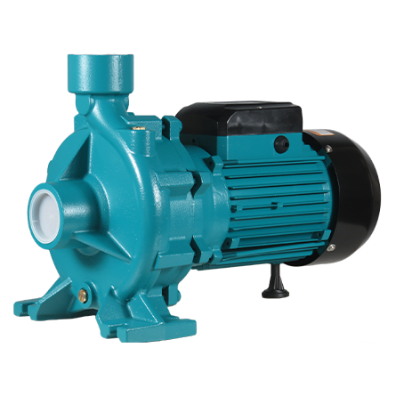
An industrial-grade hydronic circulation pump utilizes an inline centrifugal layout. Fluid enters the suction flange along the shaft axis, accelerates outward through rotating impeller vanes, and enters the expanding volute casing. This geometry transforms velocity into static working pressure, keeping fluid circulating smoothly across every branch.
Friction head follows quadratic physics inside closed loops. Doubling circulating volume through a fixed pipe diameter causes friction loss to spike nearly fourfold. Understanding this curve prevents serious sizing mistakes on commercial job sites.
Engineering Parameter
Open Fluid Transfer Applications
Closed Hydronic Systems
Primary Resistance
Static elevation lift plus dynamic pipe loss
Pure dynamic friction loss through fittings and pipes
Fluid Containment
Constantly replenished fresh fluid reservoir
Hermetically sealed, fixed volume of recirculating fluid
Suction Pressure
Dependent on atmospheric level and liquid height
Controlled by pre-pressurized expansion tanks
Hydraulic Focus
High total dynamic head with intermittent cycles
Moderate dynamic head designed for continuous duty
| Engineering Parameter | Open Fluid Transfer Applications | Closed Hydronic Systems |
|---|---|---|
| Primary Resistance | Static elevation lift plus dynamic pipe loss | Pure dynamic friction loss through fittings and pipes |
| Fluid Containment | Constantly replenished fresh fluid reservoir | Hermetically sealed, fixed volume of recirculating fluid |
| Suction Pressure | Dependent on atmospheric level and liquid height | Controlled by pre-pressurized expansion tanks |
| Hydraulic Focus | High total dynamic head with intermittent cycles | Moderate dynamic head designed for continuous duty |
Selecting an industrial circulation pump strictly by matching existing pipe diameters frequently leads to poor operating curves. Reliable hydraulic performance requires plotting calculated piping system resistance against manufacturer pump performance curves to target the optimal duty point.
Canned Wet Rotor Architecture Versus Dry Rotor Workhorses
Mechanical engineers choose between two primary mechanical pump layouts: glandless wet-rotor canned designs and traditional dry-rotor mechanical seal configurations. That selection directly dictates ongoing maintenance requirements, acoustic comfort, and long-term operating costs.
Structural Feature
Wet-Rotor Canned Pump Assembly
Dry-Rotor Mechanically Sealed Assembly
Motor Heat Dissipation
System process fluid cools the rotor chamber
External ambient airflow from motor cooling fans
Shaft Sealing Design
Hermetic containment can with zero dynamic seals
Traditional mechanical spring-loaded face seals
Radial Bearing Lubrication
Continuous lubrication via circulating water
External grease ports or sealed lifetime ball bearings
Operating Noise Level
Whisper-quiet; fluid dampens mechanical vibration
Noticeable mechanical hum from external motor fans
Ideal Application
Radiant heating, domestic hot water, compact HVAC
High-volume district heating mains, large cooling towers
| Structural Feature | Wet-Rotor Canned Pump Assembly | Dry-Rotor Mechanically Sealed Assembly |
|---|---|---|
| Motor Heat Dissipation | System process fluid cools the rotor chamber | External ambient airflow from motor cooling fans |
| Shaft Sealing Design | Hermetic containment can with zero dynamic seals | Traditional mechanical spring-loaded face seals |
| Radial Bearing Lubrication | Continuous lubrication via circulating water | External grease ports or sealed lifetime ball bearings |
| Operating Noise Level | Whisper-quiet; fluid dampens mechanical vibration | Noticeable mechanical hum from external motor fans |
| Ideal Application | Radiant heating, domestic hot water, compact HVAC | High-volume district heating mains, large cooling towers |
A modern inline wet rotor pump encases the motor rotor and shaft bearings inside a hermetic stainless steel containment can. Circulating water flows directly through this chamber, cooling electrical windings and lubricating ceramic sleeve bearings. Because this design eliminates dynamic mechanical shaft seals, it gets rid of the most common leakage failure point found on commercial jobs. When commercial facilities require motors larger than five horsepower, dry-rotor assemblies take over, offering standard motor swap flexibility and accessible mechanical overhaul options.
Intelligent Speed Modulation and Operating Modes
Modern building efficiency codes discourage outdated single-speed motors. Modern waterway circulation pump setups incorporate electronically commutated permanent magnet motors (ECM) that adjust rotational speeds automatically based on valve movements.
Speed Regulation Mode
Engineering Operating Principle
Ideal Piping Layout
Proportional Pressure
Lowers head automatically as flow decreases
Two-pipe radiator loops with thermostatic valves
Constant Pressure
Holds constant differential head across all flows
Underfloor radiant heating manifolds and balanced loops
Constant Speed
Operates at a fixed manual speed setting
Boiler primary injection loops and constant-flow mains
Temperature Differential
Adjusts flow to maintain target return temperature
Dedicated domestic hot water return circuits
| Speed Regulation Mode | Engineering Operating Principle | Ideal Piping Layout |
|---|---|---|
| Proportional Pressure | Lowers head automatically as flow decreases | Two-pipe radiator loops with thermostatic valves |
| Constant Pressure | Holds constant differential head across all flows | Underfloor radiant heating manifolds and balanced loops |
| Constant Speed | Operates at a fixed manual speed setting | Boiler primary injection loops and constant-flow mains |
| Temperature Differential | Adjusts flow to maintain target return temperature | Dedicated domestic hot water return circuits |
When thermostatic valves close across a multi-story facility, an unmodulated hydronic circulation pump forces excessive pressure against restricted pipe runs. This drives up power consumption and causes annoying high-frequency valve whistling. Advanced variable-frequency controls lower motor speed smoothly, extending mechanical life, saving energy, and maintaining balanced room comfort.
Metallurgy Selection for Diverse Working Fluids
Fluid chemistry directly governs casing and impeller metallurgy. Regular deoxygenated heating water performs reliably inside standard cast iron housings. However, domestic hot water loops introduce fresh, oxygen-saturated potable water that quickly corrodes plain cast iron surfaces.
Circulating Fluid Medium
Recommended Housing Material
Impeller Material Selection
Deoxygenated Water
Class 30 fine-grain Cast Iron
Glass-reinforced Composite (PPO/PES)
Potable Fresh Water
Lead-free Bronze or AISI 304 Stainless
Food-grade Polymer or Bronze Alloy
Chilled Glycol Mixtures
Heavy-wall AISI 304/316 Stainless
Precision-machined Stainless Steel
High-Temp Solar Thermal
Ductile Iron or Cast Stainless Steel
High-temperature Polymer or Metal Composite
| Circulating Fluid Medium | Recommended Housing Material | Impeller Material Selection |
|---|---|---|
| Deoxygenated Water | Class 30 fine-grain Cast Iron | Glass-reinforced Composite (PPO/PES) |
| Potable Fresh Water | Lead-free Bronze or AISI 304 Stainless | Food-grade Polymer or Bronze Alloy |
| Chilled Glycol Mixtures | Heavy-wall AISI 304/316 Stainless | Precision-machined Stainless Steel |
| High-Temp Solar Thermal | Ductile Iron or Cast Stainless Steel | High-temperature Polymer or Metal Composite |
Pumping propylene or ethylene glycol solutions requires careful engineering adjustments. Glycol mixtures exhibit higher dynamic viscosity and lower heat capacity than clean water. Thorough circulation pump sizing protocols must integrate kinematic viscosity correction factors to ensure motor windings remain cool under heavy thermal loads.
Step-by-Step Engineering Protocols for Circulation Pump Sizing
Locating the true Best Efficiency Point requires calculating building thermal demand alongside total frictional resistance. Skipping these engineering calculations often leads to premature pump failure.
Sizing Step
Hydraulic Parameter Target
Design and Sizing Objective
Flow Calculation
Flow derived from heat load and system delta T
Delivers sufficient heat transfer without excessive pipe velocity
Equivalent Pipe Run
Measured pipe length plus cumulative fitting losses
Quantifies total internal frictional resistance across loops
Dynamic Head Loss
Pressure loss expressed in feet or meters of head
Establishes minimum head requirement on performance curves
Cavitation Margin
Available suction head exceeding pump requirement
Prevents micro-bubble collapse, impeller pitting, and bearing wear
| Sizing Step | Hydraulic Parameter Target | Design and Sizing Objective |
|---|---|---|
| Flow Calculation | Flow derived from heat load and system delta T | Delivers sufficient heat transfer without excessive pipe velocity |
| Equivalent Pipe Run | Measured pipe length plus cumulative fitting losses | Quantifies total internal frictional resistance across loops |
| Dynamic Head Loss | Pressure loss expressed in feet or meters of head | Establishes minimum head requirement on performance curves |
| Cavitation Margin | Available suction head exceeding pump requirement | Prevents micro-bubble collapse, impeller pitting, and bearing wear |
Flow rate calculations rely on fundamental thermodynamics: thermal load divided by the product of design temperature drop, specific heat, and fluid density provides required volumetric flow. Combining this calculated flow with total equivalent piping resistance reveals the true operational duty point during circulation pump sizing procedures.
Practical Troubleshooting for Common Field Issues
Even well-designed hydronic loops encounter operational hiccups during seasonal commissioning. Catching these mechanical issues early prevents costly downtime.
Field Symptom
Primary Root Cause
Corrective Engineering Action
Rattling Gravel Sound
Entrained air pockets or low suction cavitation
Bleed air via automatic air vents; adjust expansion tank pressure
High-Pitched Pipe Hiss
High fluid velocity through throttled valves
Switch pump control setting to proportional pressure mode
Uneven Loop Heating
Insufficient pump head or unbalanced branch runs
Rebalance circuit balancing valves; verify pump duty point sizing
Excessive Motor Heat
Debris locked rotor or dry-running bearings
Flush piping debris; clean magnetic separator; verify fluid fill
| Field Symptom | Primary Root Cause | Corrective Engineering Action |
|---|---|---|
| Rattling Gravel Sound | Entrained air pockets or low suction cavitation | Bleed air via automatic air vents; adjust expansion tank pressure |
| High-Pitched Pipe Hiss | High fluid velocity through throttled valves | Switch pump control setting to proportional pressure mode |
| Uneven Loop Heating | Insufficient pump head or unbalanced branch runs | Rebalance circuit balancing valves; verify pump duty point sizing |
| Excessive Motor Heat | Debris locked rotor or dry-running bearings | Flush piping debris; clean magnetic separator; verify fluid fill |
Installing an inline magnetic dirt separator directly upstream from an efficient wet rotor pump catches black magnetite sludge before metallic debris enters the magnetic rotor chamber, safeguarding internal ceramic bearings.
Industrial Manufacturing Standards and OEM Supply Chains
Procuring dependable commercial pumping equipment requires an engineering manufacturing partner with proven machining precision and strict quality controls. Global distributors and mechanical contractors demand uniform casting tolerances, certified motor insulation, and validated performance curves.
Industrial procurement through Flyaway delivers reliable manufacturing standards and robust supply chain integration. Flyaway operates high-volume production facilities featuring automated stator winding lines, computerized dynamic rotor balancing benches, and multi-station closed-loop hydraulic testing facilities. Supporting extensive OEM and ODM customization programs, Flyaway fabricates every waterway circulation pump under strict international performance and electrical safety testing standards. Equipment distributors and project contractors secure reliable batch-to-batch consistency, verified hydraulic efficiency, and resilient supply chain fulfillment for global commercial distribution.