 EN
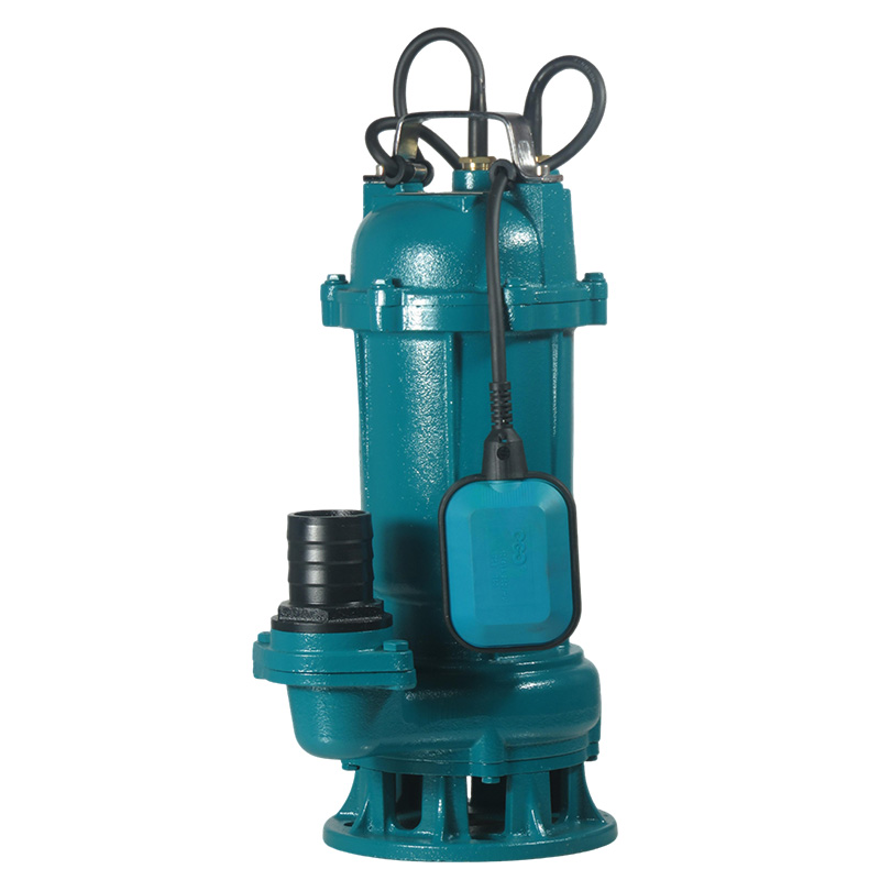
Commercial Submersible Sump Pump Engineering and Heavy Drainage Solutions
Drainage operations on municipal, civil, and industrial jobsites rarely match the clean scenarios depicted in basic design handbooks. Real-world sumps constantly battle suspended silica sand, fibrous municipal debris, abrasive grit, and continuous fluid inflows. Under these unforgiving conditions, surface-mounted dewatering equipment frequently suffers from suction line cavitation, priming failures, and mechanical seal starvation.
A heavy-duty submersible pump resolves these mechanical bottlenecks by operating submerged directly inside the fluid reservoir. Submerged positioning harnesses surrounding water pressure to feed the impeller eye continuously, eliminating physical suction lift issues and dramatically cutting equipment footprint requirements. However, continuous duty cycles demand exact synchronization between physical wet-end metallurgy, basin volume design, and hydraulic performance curves.
Overcoming Harsh Pit Dewatering Challenges
Submerged pit dewatering introduces mechanical and thermal stresses that quickly destroy light-duty pumping units. When water levels decline during rapid drawdowns, motors risk thermal cutouts unless secondary cooling safeguards exist. Meanwhile, abrasive sediments scour mechanical wear plates, widening running clearances and degrading dynamic pressure delivery.
Operational Hurdle
Physical Root Cause
Preventive Engineering Action
Low-Level Thermal Cutout
Liquid drawdowns expose the motor stator to air, halting convective cooling
Deploy a drainage pump equipped with an internal fluid cooling jacket
Rapid Impeller Wear
Suspended silica sand cuts into soft metals via high-velocity scouring
Specify high-chrome alloy impellers hardened past 55 HRC
Suction Inlet Blockage
Fibrous trash, plastics, and dense solids consolidate around the strainer basket
Utilize non-clogging vortex hydraulics or active shredder cutter rings
Shaft Deflection Fatigue
Extended operation far to the left or right of the Best Efficiency Point
Match pipe discharge friction losses to dynamic head output ratings
| Operational Hurdle | Physical Root Cause | Preventive Engineering Action |
|---|---|---|
| Low-Level Thermal Cutout | Liquid drawdowns expose the motor stator to air, halting convective cooling | Deploy a drainage pump equipped with an internal fluid cooling jacket |
| Rapid Impeller Wear | Suspended silica sand cuts into soft metals via high-velocity scouring | Specify high-chrome alloy impellers hardened past 55 HRC |
| Suction Inlet Blockage | Fibrous trash, plastics, and dense solids consolidate around the strainer basket | Utilize non-clogging vortex hydraulics or active shredder cutter rings |
| Shaft Deflection Fatigue | Extended operation far to the left or right of the Best Efficiency Point | Match pipe discharge friction losses to dynamic head output ratings |
Specifying a rugged submersible sump pump tailored to actual solids characteristics prevents unscheduled pit teardowns. Mechanical contractors must evaluate dynamic site inflows rather than relying on static pit measurements before procurement.
Matching Fluid Dynamics to Impeller and Metallurgy
Selecting equipment based purely on rated motor horsepower leads to frequent jobsite failures. Fluid viscosity, chemical corrosive potential, and suspended solids concentration dictate wet-end longevity. Pumping groundwater requires high hydraulic efficiency, whereas industrial runoff laced with corrosive salts or tailings mandates chemically inert casting alloys.
Fluid Classification
Suspended Solids Profile
Optimal Impeller & Alloy Selection
Groundwater Drainage
Clean seepage, zero abrasive solids, neutral pH
High-efficiency closed impeller, ductile cast iron casing
Stormwater Runoff
Intermittent sand, fine silt, surface organic debris
Semi-open wear-resistant impeller, hardened ductile iron
Industrial Process Sump
Corrosive chemicals, acidic wash water, fluctuating pH
Complete AISI 316 stainless steel or duplex alloy wet end
Wastewater Sludge
Stringy organic matter, paper fibers, heavy mud
High-torque septic tank pump with recessed vortex impeller
| Fluid Classification | Suspended Solids Profile | Optimal Impeller & Alloy Selection |
|---|---|---|
| Groundwater Drainage | Clean seepage, zero abrasive solids, neutral pH | High-efficiency closed impeller, ductile cast iron casing |
| Stormwater Runoff | Intermittent sand, fine silt, surface organic debris | Semi-open wear-resistant impeller, hardened ductile iron |
| Industrial Process Sump | Corrosive chemicals, acidic wash water, fluctuating pH | Complete AISI 316 stainless steel or duplex alloy wet end |
| Wastewater Sludge | Stringy organic matter, paper fibers, heavy mud | High-torque septic tank pump with recessed vortex impeller |
Selecting an optimized sump pump configuration protects downstream piping from dynamic pressure shocks while stabilizing electrical consumption during prolonged runtimes.
Wet Well Geometry and Mechanical Control Protocols
A dependable submersible pump installation relies on proper collection basin geometry just as much as internal motor construction. Poorly designed sumps generate stagnant dead zones where heavy sediments settle, reducing usable fluid storage volume and causing rapid motor start-stop cycling.
Wet Well Parameter
Recommended Engineering Metric
Failure Mode Prevented
Cycle Frequency Limits
Maximum 10 to 15 starts per hour under continuous operational inflow
Motor winding insulation degradation and thermal switch trips
Float Switch Clearance
Minimum 200 mm physical clearance from discharge pipes and wet walls
Tether entanglement, false level signals, dry running pump burnout
Anti-Vortex Floor Sump
Steep 45-degree sloped basin benching directed toward pump intake
Sludge accumulation, anaerobic gas buildup, suction air entrapment
Dual Rail Guide System
Heavy-duty stainless steel guide rails with slide-connection brackets
Manual pit entry hazards, cumbersome disconnects during servicing
| Wet Well Parameter | Recommended Engineering Metric | Failure Mode Prevented |
|---|---|---|
| Cycle Frequency Limits | Maximum 10 to 15 starts per hour under continuous operational inflow | Motor winding insulation degradation and thermal switch trips |
| Float Switch Clearance | Minimum 200 mm physical clearance from discharge pipes and wet walls | Tether entanglement, false level signals, dry running pump burnout |
| Anti-Vortex Floor Sump | Steep 45-degree sloped basin benching directed toward pump intake | Sludge accumulation, anaerobic gas buildup, suction air entrapment |
| Dual Rail Guide System | Heavy-duty stainless steel guide rails with slide-connection brackets | Manual pit entry hazards, cumbersome disconnects during servicing |
Deploying alternating duplex panels alongside a balanced submersible sump pump layout ensures even wear across duty and standby units, guaranteeing operational redundancy during peak stormwater surges.
Hydraulic Head Calculations for Deep Pit Systems
Field failures frequently happen when engineering teams calculate static lift but disregard friction losses created by valves, check assemblies, and pipe wall resistance. Running a drainage pump too far out on its head curve overloads the motor, whereas excessive system backpressure leads to dead-heading and mechanical seal ruin.
System Parameter
Sizing Verification Metric
Mechanical Risk Mitigated
Flow Velocity
1.5 to 2.5 meters per second inside main discharge piping
Solids settlement in vertical runs, dynamic hydraulic friction head
Non-Return Valves
Full-port quiet swing check valves installed horizontally
Destructive water hammer pressure spikes, reverse impeller spin
Total Dynamic Head
Calculated static vertical lift plus cumulative piping friction losses
Motor overload, bearing housing overheating, shaft snap
Suction Strainer Area
Minimum free intake passage matching five times discharge diameter
Cavitation erosion on the impeller eye, restricted suction delivery
| System Parameter | Sizing Verification Metric | Mechanical Risk Mitigated |
|---|---|---|
| Flow Velocity | 1.5 to 2.5 meters per second inside main discharge piping | Solids settlement in vertical runs, dynamic hydraulic friction head |
| Non-Return Valves | Full-port quiet swing check valves installed horizontally | Destructive water hammer pressure spikes, reverse impeller spin |
| Total Dynamic Head | Calculated static vertical lift plus cumulative piping friction losses | Motor overload, bearing housing overheating, shaft snap |
| Suction Strainer Area | Minimum free intake passage matching five times discharge diameter | Cavitation erosion on the impeller eye, restricted suction delivery |
Accurately calculating total dynamic head guarantees that the selected sump pump operates within its preferred operating zone, preserving bearing life and cutting utility consumption over years of continuous operation.
High-Performance Metallurgy for Demanding Sumps
Aggressive mining pits, chemical transfer stations, and coastal drainage infrastructure expose fluid handling systems to severe chemical and mechanical wear. Standard cast iron casings thin rapidly in acidic liquids, leading to outer casing breaches and motor flooding.
Application Environment
Chemical and Abrasive Stressors
Recommended Metallurgy
Mine Dewatering
High-concentration quartz grit, acidic drainage water
Double silicon-carbide seals, high-chrome white iron wet ends
Marine & Seawater Sumps
High chloride exposure, galvanic corrosion potential
Nickel aluminum bronze or super duplex stainless steel
Agricultural Runoff Pits
Highly corrosive ammonia, fibrous animal bedding, silage
Heavy-duty septic tank pump with tungsten-carbide mechanical seals
Commercial Basement Sumps
Neutral seepage, lint, intermittent greywater discharge
Heavy-walled cast iron casing with stainless steel motor housing
| Application Environment | Chemical and Abrasive Stressors | Recommended Metallurgy |
|---|---|---|
| Mine Dewatering | High-concentration quartz grit, acidic drainage water | Double silicon-carbide seals, high-chrome white iron wet ends |
| Marine & Seawater Sumps | High chloride exposure, galvanic corrosion potential | Nickel aluminum bronze or super duplex stainless steel |
| Agricultural Runoff Pits | Highly corrosive ammonia, fibrous animal bedding, silage | Heavy-duty septic tank pump with tungsten-carbide mechanical seals |
| Commercial Basement Sumps | Neutral seepage, lint, intermittent greywater discharge | Heavy-walled cast iron casing with stainless steel motor housing |
Upgrading wear components before deployment prevents catastrophic casing penetration, ensuring that your submersible pump fleet delivers consistent output under grueling environmental conditions.
Preventive Maintenance Schedules for Continuous Operation
Proactive diagnostic regimens eliminate costly emergency wet-well cleanouts. Consistent inspection records identify gradual seal wear, allowing planned component replacement before water penetrates high-voltage motor windings.
Inspection Frequency
Maintenance Action Item
Target Diagnostic Metric
Monthly Schedule
Clean surface grease and fibrous buildup from float controls
Float switches move unobstructed throughout full travel range
Quarterly Schedule
Conduct electrical insulation resistance testing using a megohmmeter
Stator winding resistance reading consistently exceeds 20 Megohms
Semi-Annual Schedule
Inspect non-return check valves and emergency discharge isolation
Flapper seating seals tightly without backward backflow leakage
Annual Schedule
Drain and sample the dynamic mechanical seal oil reservoir
Oil sample remains clear without milky water-emulsion contamination
| Inspection Frequency | Maintenance Action Item | Target Diagnostic Metric |
|---|---|---|
| Monthly Schedule | Clean surface grease and fibrous buildup from float controls | Float switches move unobstructed throughout full travel range |
| Quarterly Schedule | Conduct electrical insulation resistance testing using a megohmmeter | Stator winding resistance reading consistently exceeds 20 Megohms |
| Semi-Annual Schedule | Inspect non-return check valves and emergency discharge isolation | Flapper seating seals tightly without backward backflow leakage |
| Annual Schedule | Drain and sample the dynamic mechanical seal oil reservoir | Oil sample remains clear without milky water-emulsion contamination |
Following rigorous service schedules extends the operational life of every drainage pump on site, protecting capital equipment investments and avoiding catastrophic basement or pit flooding.
Engineering Precision and Global Manufacturing Support
Field dependability across challenging drainage installations requires advanced casting precision, strict dynamic rotor balancing, and certified wet-pit performance validation. Reliable dewatering operations depend on fluid machinery engineered to handle continuous abrasive and hydraulic stress without unexpected motor shutdowns.
Flyaway delivers comprehensive fluid handling equipment, industrial dewatering machinery, and robust submersible pump configurations built for exacting international markets. Utilizing multi-axis CNC machining bays, automated stator manufacturing, and computerized hydraulic test pits, Flyaway validates pressure limits, insulation barriers, and precise flow-head curves on every unit prior to delivery.
For international pump distributors, engineering procurement contractors, and regional equipment brands, Flyaway provides agile OEM and ODM manufacturing partnerships. Backed by extensive material casting capabilities, strict ISO 9001 and CE compliance, and dependable containerized logistics coordination, Flyaway supplies commercial submersible sump pump and industrial drainage pump solutions that maximize dewatering uptime across global infrastructure projects.