 EN
Domestic Water Pump: Sizing & Selection Guide
Selecting an appropriate domestic water pump requires evaluating hydraulic mechanics rather than relying on motor horsepower ratings printed on packaging labels. Oversized motors waste electrical power and generate excessive pipe vibration, while undersized units struggle to provide adequate shower pressure whenever multiple household taps open simultaneously. Matching hardware to the primary intake source, piping layout, and continuous delivery demands prevents premature mechanical seal failures and persistent pressure fluctuations.
Plumbing contractors, property managers, and hardware distributors prevent field warranty claims by establishing physical hydraulic parameters before purchasing hardware. Sizing pumping machinery around verified discharge demand guarantees reliable household water delivery across daily usage peaks.
Matching Water Sources to Primary Hydraulic Families
Domestic water infrastructure relies on diverse water sources, each demanding a specialized hydraulic design. Misapplying equipment categories leads to chronic priming failures, seal wear, and motor burnout.
Supply Source Profile
Primary Operating Challenge
Recommended Equipment Profile
Municipal Main Line
Inadequate or fluctuating municipal line pressure
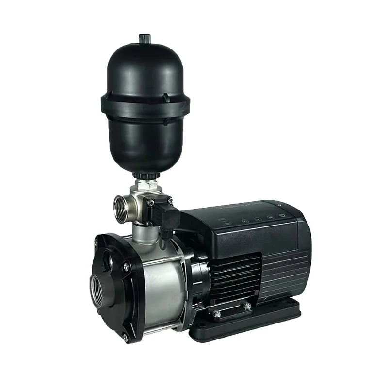
Compact multistage household booster pump with integrated pressure controls
Shallow Dug Well or Cistern
Suction lift limitations and air ingress risks
Self-priming jet pump fitted with airtight suction piping and a foot valve
Deep Ground Borehole
Dynamic water level drops exceeding eight meters
Multistage submersible well pump suspended directly within the water column
Rainwater Collection Basin
Suspended organic debris and fluctuating tank levels
Submersible utility pump or surface transfer pump equipped with fine inlet filtration
Groundwater Basement Sump
Ingress of muddy runoff, silt, and occasional solids
Submersible drainage pump engineered with open vortex impellers
| Supply Source Profile | Primary Operating Challenge | Recommended Equipment Profile |
|---|---|---|
| Municipal Main Line | Inadequate or fluctuating municipal line pressure | Compact multistage household booster pump with integrated pressure controls |
| Shallow Dug Well or Cistern | Suction lift limitations and air ingress risks | Self-priming jet pump fitted with airtight suction piping and a foot valve |
| Deep Ground Borehole | Dynamic water level drops exceeding eight meters | Multistage submersible well pump suspended directly within the water column |
| Rainwater Collection Basin | Suspended organic debris and fluctuating tank levels | Submersible utility pump or surface transfer pump equipped with fine inlet filtration |
| Groundwater Basement Sump | Ingress of muddy runoff, silt, and occasional solids | Submersible drainage pump engineered with open vortex impellers |
Surface pumps draw water through negative suction pressure, creating physical vulnerabilities whenever intake depth exceeds seven meters. Deep underground sources demand a submersible well pump that pushes liquid upward under positive displacement, completely removing suction lift limitations and eliminating pump priming routines.
Calculating Flow Rates Through Simultaneous Household Demand
Calculating system capacity requires determining realistic peak simultaneous consumption rather than tallying every installed plumbing fixture in the building. An accurately sized domestic water pump provides stable flow even during concurrent bathroom and utility usage.
Household Usage Profile
Simultaneous Active Fixtures
Estimated Peak Flow Target
Single Bathroom Residence
One shower, one kitchen sink faucet
20 to 30 Liters / min
Two Bathroom Family Home
Two showers, kitchen sink, laundry washing machine
35 to 55 Liters / min
Luxury Multi-Level Villa
Three showers, garden irrigation line, kitchen fixture
60 to 90 Liters / min
Light Agricultural Homestead
Domestic fixtures, livestock water troughs, washdown lines
70 to 110 Liters / min
| Household Usage Profile | Simultaneous Active Fixtures | Estimated Peak Flow Target |
|---|---|---|
| Single Bathroom Residence | One shower, one kitchen sink faucet | 20 to 30 Liters / min |
| Two Bathroom Family Home | Two showers, kitchen sink, laundry washing machine | 35 to 55 Liters / min |
| Luxury Multi-Level Villa | Three showers, garden irrigation line, kitchen fixture | 60 to 90 Liters / min |
| Light Agricultural Homestead | Domestic fixtures, livestock water troughs, washdown lines | 70 to 110 Liters / min |
Underestimating system flow rates produces dramatic pressure drops when secondary valves open. Conversely, excessive pump capacity causes frequent rapid cycling, pipe hammering, and accelerated contact erosion across mechanical pressure switches.
Total Dynamic Head and Friction Loss Analysis
A dependable residential water pump must overcome total dynamic head, which represents the combined resistance of physical elevation, friction across plumbing conduits, and necessary terminal discharge pressure.
Head Parameter
Calculation Factor
Technical Sizing Strategy
Static Elevation Lift
Vertical measurement from water surface to highest fixture
Measure vertical height directly; disregard horizontal pipe routing
Required Fixture Pressure
Residual pressure required at showerheads and faucets
Plan for 2.5 to 3.5 bar (25 to 35 meters head equivalent) for domestic comfort
Pipe Friction Losses
Internal fluid drag across pipe walls, elbows, and valves
Size distribution pipes to keep fluid velocity under 1.5 meters per second
In-Line Component Losses
Restriction across whole-house filters and water softeners
Factor an additional 0.5 to 1.0 bar pressure drop across filtration media
| Head Parameter | Calculation Factor | Technical Sizing Strategy |
|---|---|---|
| Static Elevation Lift | Vertical measurement from water surface to highest fixture | Measure vertical height directly; disregard horizontal pipe routing |
| Required Fixture Pressure | Residual pressure required at showerheads and faucets | Plan for 2.5 to 3.5 bar (25 to 35 meters head equivalent) for domestic comfort |
| Pipe Friction Losses | Internal fluid drag across pipe walls, elbows, and valves | Size distribution pipes to keep fluid velocity under 1.5 meters per second |
| In-Line Component Losses | Restriction across whole-house filters and water softeners | Factor an additional 0.5 to 1.0 bar pressure drop across filtration media |
Adding static elevation, friction resistance, and target terminal pressure produces the total dynamic head. Cross-referencing this head value against the manufacturer performance curve identifies the true operating point. Selecting equipment operating near the center of the hydraulic efficiency curve prevents motor overloading and prolongs mechanical bearing lifespan.
Surface Jet Pumps Versus Submersible Configurations
Installation layout and physical source depth determine whether surface-mounted jet units or downhole submersibles offer the most reliable mechanical configuration.
Engineering Factor
Surface-Mounted Jet Pump Systems
Submersible Borehole Pump Systems
Maximum Suction Lift
Structurally restricted to seven or eight meters
Operates submerged; zero suction lift limitation
Acoustic Footprint
Noticeable mechanical motor noise during operation
Virtually silent operation due to acoustic dampening from water
Environmental Exposure
Requires weatherproofing shelter and winter freeze protection
Submerged below the frost line; immune to surface atmospheric extremes
Priming Maintenance
Susceptible to suction line air leaks and lost-prime conditions
Continuously primed by surrounding liquid column
Installation Accessibility
Rapid surface access for valve, seal, and switch servicing
Requires hoisting drop pipe and electrical cabling for maintenance
| Engineering Factor | Surface-Mounted Jet Pump Systems | Submersible Borehole Pump Systems |
|---|---|---|
| Maximum Suction Lift | Structurally restricted to seven or eight meters | Operates submerged; zero suction lift limitation |
| Acoustic Footprint | Noticeable mechanical motor noise during operation | Virtually silent operation due to acoustic dampening from water |
| Environmental Exposure | Requires weatherproofing shelter and winter freeze protection | Submerged below the frost line; immune to surface atmospheric extremes |
| Priming Maintenance | Susceptible to suction line air leaks and lost-prime conditions | Continuously primed by surrounding liquid column |
| Installation Accessibility | Rapid surface access for valve, seal, and switch servicing | Requires hoisting drop pipe and electrical cabling for maintenance |
For shallow cisterns and surface tanks, a surface-mounted household booster pump simplifies routine mechanical switch inspections. Deep well systems require a dedicated submersible well pump to bypass atmospheric suction barriers and protect operations against seasonal groundwater table drops.
Pressure Tank Sizing and Pump Cycling Controls
Uncontrolled motor start-stop cycling degrades motor windings and damages contact points. Integrating pressure tanks and automated electronic controllers creates a stable, continuous delivery buffer.
Control Architecture
Operating Principle
Core Engineering Advantage
Traditional Pressure Switch & Tank
Mechanical switch activates pump across preset cut-in and cut-out points
Buffers minor leaks; dampens hydraulic pressure surges
Electronic Flow Controller
Flow sensor monitors water movement, running pump continuously during use
Eliminates heavy steel pressure tanks; prevents pump dry running
Variable Frequency Drive (VFD)
Inverter adjusts motor rotational speed to match changing tap demand
Maintains exact constant pressure; minimizes power usage
| Control Architecture | Operating Principle | Core Engineering Advantage |
|---|---|---|
| Traditional Pressure Switch & Tank | Mechanical switch activates pump across preset cut-in and cut-out points | Buffers minor leaks; dampens hydraulic pressure surges |
| Electronic Flow Controller | Flow sensor monitors water movement, running pump continuously during use | Eliminates heavy steel pressure tanks; prevents pump dry running |
| Variable Frequency Drive (VFD) | Inverter adjusts motor rotational speed to match changing tap demand | Maintains exact constant pressure; minimizes power usage |
A diaphragm pressure tank stores pressurized water, meeting minor consumption needs without triggering the motor. Sizing the pressure tank to ensure minimum motor run cycles of sixty to ninety seconds dissipates winding heat and extends mechanical relay life on any residential water pump.
Metallurgical Durability and Electrical Specifications
Aggressive water chemistry, dissolved mineral hardness, and electrical voltage irregularities accelerate internal hardware degradation. Evaluating component metallurgy ensures dependable multi-year operational lifespans.
Subsystem Component
Material Standard
Engineering Justification
Motor Stator and Windings
100% pure electrolytic copper wire with Class F insulation
Prevents thermal breakdown under elevated ambient operating temperatures
Hydraulic Impeller
Machined brass, PPO engineered thermoplastic, or AISI 304
Resists hydraulic cavitation erosion and abrasive silt scoring
Mechanical Shaft Seal
Silicon carbide to carbon with NBR or fluoroelastomer seating
Prevents pressurized water ingress into internal motor bearings
Pump Volute Casing
High-tensile cast iron treated with anti-rust electrophoresis
Resists hydraulic pressure stress and aggressive atmospheric humidity
| Subsystem Component | Material Standard | Engineering Justification |
|---|---|---|
| Motor Stator and Windings | 100% pure electrolytic copper wire with Class F insulation | Prevents thermal breakdown under elevated ambient operating temperatures |
| Hydraulic Impeller | Machined brass, PPO engineered thermoplastic, or AISI 304 | Resists hydraulic cavitation erosion and abrasive silt scoring |
| Mechanical Shaft Seal | Silicon carbide to carbon with NBR or fluoroelastomer seating | Prevents pressurized water ingress into internal motor bearings |
| Pump Volute Casing | High-tensile cast iron treated with anti-rust electrophoresis | Resists hydraulic pressure stress and aggressive atmospheric humidity |
Electrical parameters require precise alignment with local utility grids. Matching single-phase voltage thresholds, incorporating motor thermal overload protectors, and providing grounded circuits prevents motor burnout during grid fluctuations. Selecting a rugged domestic water pump demands verified metallurgical specifications suited to local water chemistry.
Pre-Procurement Engineering Evaluation Protocol
Plumbing engineers and procurement specialists eliminate hardware selection mistakes by utilizing an orderly verification workflow before placing equipment purchase orders.
Evaluation Stage
Primary Inspection Target
Technical Documentation Output
Fluid Source Verification
Static water depth, seasonal drawdown, and water clarity
Permitted pump category and casing metallurgy checklist
Hydraulic Load Assessment
Simultaneous fixture draw and calculated total dynamic head
System duty point plotted on manufacturer performance curve
Control Integration Review
Tank drawdown volume and automated pressure switch thresholds
System schematic illustrating safety valves and pressure vessels
Electrical Safety Audit
Available line voltage, phase consistency, and breaker amperage
Motor thermal protection and grounding wiring specification
| Evaluation Stage | Primary Inspection Target | Technical Documentation Output |
|---|---|---|
| Fluid Source Verification | Static water depth, seasonal drawdown, and water clarity | Permitted pump category and casing metallurgy checklist |
| Hydraulic Load Assessment | Simultaneous fixture draw and calculated total dynamic head | System duty point plotted on manufacturer performance curve |
| Control Integration Review | Tank drawdown volume and automated pressure switch thresholds | System schematic illustrating safety valves and pressure vessels |
| Electrical Safety Audit | Available line voltage, phase consistency, and breaker amperage | Motor thermal protection and grounding wiring specification |
Completing an initial hydraulic calculation prevents costly field modifications and ensures that the installed domestic water pump meets real-world domestic flow demands.
Precision Manufacturing and Supply Chain Infrastructure
Sustained domestic water reliability requires industrial-grade manufacturing discipline, precision motor engineering, and comprehensive quality control. Partnering with seasoned manufacturing facilities ensures that pump specifications reflect true testing bench performance rather than theoretical catalog estimates.
Specializing in domestic, agricultural, and industrial fluid movement systems, Flyaway provides equipment distributors, private label brands, and engineering procurement teams with advanced OEM and ODM pump manufacturing solutions. Production infrastructure encompasses automated CNC machining centers, automated motor winding, computerized dynamic rotor balancing, and multi-point pressure testing across surface-mounted units and submersible configurations. Built with 100% pure copper motor cores, electrophoretic cast iron casings, wear-resistant brass impellers, and integrated thermal overload protection, Flyaway fluid equipment provides proven reliability for residential pressure boosting, private wells, and municipal distribution networks worldwide.